- English
- Español
- Português
- русский
- Français
- 日本語
- Deutsch
- tiếng Việt
- Italiano
- Nederlands
- ภาษาไทย
- Polski
- 한국어
- Svenska
- magyar
- Malay
- বাংলা ভাষার
- Dansk
- Suomi
- हिन्दी
- Pilipino
- Türkçe
- Gaeilge
- العربية
- Indonesia
- Norsk
- تمل
- český
- ελληνικά
- український
- Javanese
- فارسی
- தமிழ்
- తెలుగు
- नेपाली
- Burmese
- български
- ລາວ
- Latine
- Қазақша
- Euskal
- Azərbaycan
- Slovenský jazyk
- Македонски
- Lietuvos
- Eesti Keel
- Română
- Slovenski
- मराठी
- Srpski језик

Products
- Unpowered Roller Conveyor Series
- Scissor Type Hydraulic Lifting Table Series
- Intelligent Factory Furniture Production Line Series
- Intelligent Packaging Line Series
- Powered Belt Conveyor Series
- Intelligent Factory Furniture Production Line Series Single Machine
- Roller Series
- Door Solution
- Automatic Plate Cleaning Machine


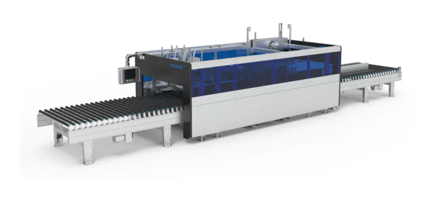
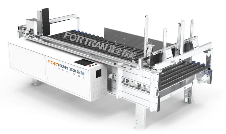
Pro Automatic Box Closing Machine
You can rest assured to buy Pro Automatic Box Closing Machine from our factory. The conveying rollers use imported PVC rubber sleeves, which are both flexible and durable;
Send Inquiry
Product Description
Machine Image
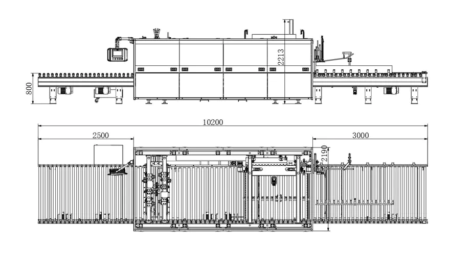
Machine specifications
| Dimensions L*W*H(mm) | Machine self-weight(kg) | Power supply(kW) | Conveying load (kg) | Working height(mm) |
| 10200*2200*2260 | Around 3200kg | 9 | 50 | 800±50 |
Processing Parameters
| Carton Processing Length(mm) | Carton Processing Width(mm) | Carton Processing Height(mm) | Sealing Efficiency (cycles/min) | Thickness of Corrugated Paper (mm) |
| 300-2900 | 200-1200 | (Wooden Panel thickness 18) 20-280 | 4-8 | 2.5-6 |
Product features
1.Core components: Eva fast-drying hot melt glue machine; servo motor; planetary reducer; laser rangefinder; synchronous belt; pillow block bearing; variable frequency motor; worm gear reducer;
2.The conveying rollers use imported PVC rubber sleeves, which are both flexible and durable;
3.The linear mechanism of the case sealer is guided by precision linear guides, ensuring high reliability and durability;
4.The power for the clamps and glue guns is provided by high-precision servo motors, which are easy to control and enhance the precision of the equipment;
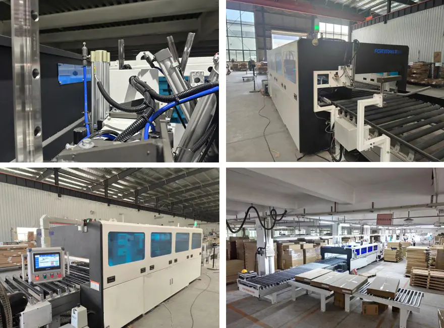
5.The machine can be used as a standalone unit or integrated with a custom home packaging line, offering versatile and flexible usage options.
Function
1.Usage
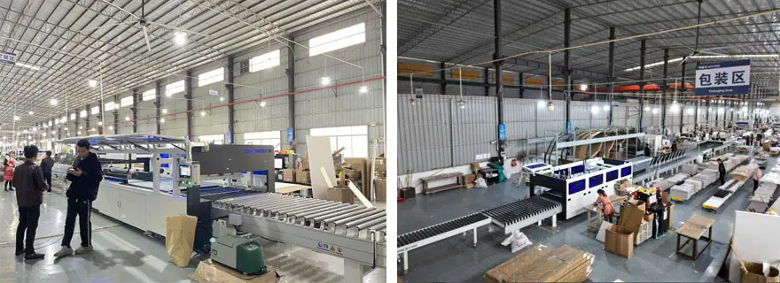
A.This Pro Automatic Box Closing Machine is used for sealing high-end furniture packaging boxes.
B.This equipment is used for sealing cartons of models M/A-0410 and M/A-0419.
C.The bottom of the carton is first glued, then the items to be packaged and the padding materials are placed inside, followed by machine sealing.
2. General Working Principle
The entire equipment is divided into five sections: the measuring machine section, the feeding buffer machine section, the tunnel sealer section, the transition machine section, and the pusher sealer section.
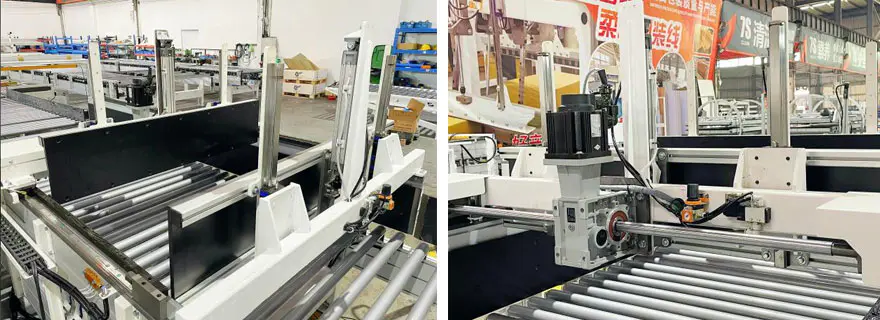
A.During operation, the packaged cartons, with the items filled inside, enter from the measuring machine section along the reference edge. The width sensor at the entrance roughly measures the width of the carton. When the carton reaches the end of the measuring machine section, it is stopped by a baffle device. The active clamp device then accurately measures the width of the carton, and the high-pressure plate device accurately measures the height of the carton. After that, the carton moves from the measuring machine section through the feeding buffer machine section to the entrance of the tunnel sealer section.
B.When the carton enters the tunnel sealer section, the glue gun at the entrance applies hot melt adhesive along the length of the carton. It then passes through the sealing channel, which consists of a folding rod assembly, pressing mechanism, side belt mechanism, and counterweight belt mechanism—completing the sealing of the long side.
C.The carton, with its long side sealed, moves into the transition machine section and is stopped by the front baffle device at the entrance of the pusher sealer section. The first short side is then glued and sealed by the spraying device, front pressing plate device, and front sealing plate device. After the first short side is sealed, the carton enters the pusher sealer section and moves backward, where it is stopped by the rear baffle device. The second short side is then glued and sealed by the spraying device, rear pressing plate device, and rear sealing plate device. At this point, the entire sealing process of the carton is completed, and it rolls out from the pusher sealer section.
D.This carton sealing method, which recognizes the width of the box, can effectively seal cartons of different sizes during the feeding process without the need to input the dimensions of the boxes.
E.For batch sealing of cartons with the same dimensions, the equipment can switch to batch mode. After measuring the width of the first carton and applying this value to the entire series, the tunnel sealer section adjusts the channel size and maintains it unchanged, thereby improving the sealing efficiency. The maximum rate can reach up to 8 packages per minute.
Functional structure
| No. | Item | Feature |
| 1 | Front section feeder | Achieve the feeding function of packages, quickly, accurately, and efficiently delivering packages to the designated positions. The main beam is made of carbon steel and coated with plastic. To ensure that packages are accurately aligned, a fixed guidance and alignment mechanism is used to guide the packages into position |
| 2 | Height measuring device | Aluminum pressing blocks are employed to measure the height of the packages through electronic scale sensors and pneumatic cylinders, and the data is then transmitted back |
| 3 | Cover | Enhancing the aesthetic appeal of the equipment while also providing a certain degree of protection, the overall structure is primarily made of bent carbon steel plates coated with plastic. It is further enhanced with specialized aluminum profiles and royal blue acrylic panels. |
| 4 | Rack | The machine frame is fabricated by welding rectangular tubes and steel plates, followed by precision machining. This ensures high assembly accuracy and operational precision, guaranteeing a long service life and good stability of the equipment |
| 5 | Gland device | Effectively holds down the top cover of the carton, preparing for the subsequent sealing process. |
| 6 | Front and Rear baffles | Achieves package positioning. Linear bearings, in conjunction with chrome-plated shafts, provide linear guidance. Multi-stage pneumatic cylinders are controlled separately and, in combination with the gluing system, achieve two-stage height adjustment. This ensures both the quality of the gluing process and effectively holds the package in a specific position for accurate positioning. |
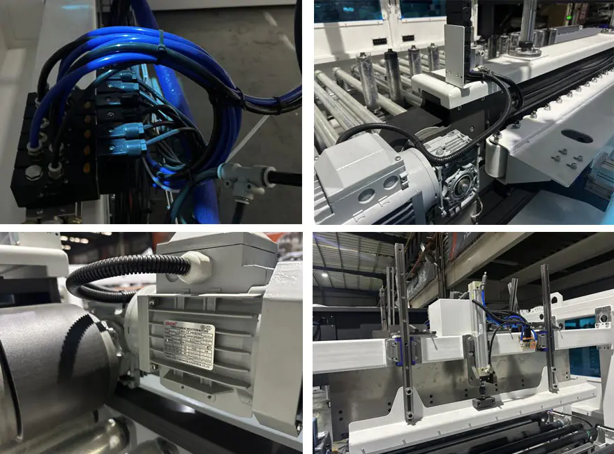
| 7 | Width measurement device | The horizontal power system employs high-precision motors in conjunction with reducers to ensure the stability of the transmission system. It is primarily responsible for folding down the top flaps of the carton to complete the sealing action. The mechanism uses linear guides to direct linear motion, with power provided by pneumatic cylinders and multiple speed control valves regulating the air circuit to achieve rapid and stable operation. |
| 8 | Double cylinder pushing plate mechanical parts | It is primarily responsible for folding down the top flaps of the carton to complete the sealing action. The mechanism uses linear guides to direct linear motion, powered by pneumatic cylinders and regulated by multiple speed control valves in the air circuit to achieve rapid and stable operation. |
| 9 | Gland mechanism | It is mainly responsible for securing the top cover of the carton to prevent the package from moving. The mechanism uses linear guides to direct linear motion, and the eccentric design of the pneumatic cylinder provides better stabilization of the package. |
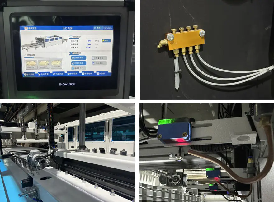
| 10 | Short edge adhesive spraying system | The guide rail is responsible for linearly guiding the entire mechanism back and forth. A high-precision servo motor provides a stable power source, and the use of a well-known domestic brand of planetary reducer further ensures reliable long-term power output. The linear guide is installed in an inverted position to prevent it from being sprayed with glue, ensuring clean and stable guidance. |
| 11 | Rear discharge machine | To achieve the function of package discharge, a dual-stage power system is used to quickly, accurately, and efficiently deliver the package. The main beam is made of carbon steel and coated with plastic. |
| 12 | Glue machine system | The Eva fast-drying hot melt glue machine can achieve both continuous and intermittent glue spraying. It is fully functional, easy to set up, and convenient to operate. |
| 13 | Down pressing mechanism | The servo motor drives the reducer to rotate the elevator, achieving precise vertical positioning. Pneumatic cylinders are used to reduce the weight and compact the package, ensuring stable and smooth forward movement. |
| 14 | Lateral pressure group | The pneumatic cylinders and linear guides move in and out to position and press the cardboard. The Teflon material prevents glue from sticking, ensuring better compression of the cardboard. |
| 15 | Side Support Assembly | The servo motor drives the reducer to rotate the gears, with linear guides providing the transmission, achieving precise side positioning. The side alignment section uses Teflon rollers to ensure consistent speed. |
| 16 | Middle Section Sealing Part | The middle section roller transmission uses a dual-stage power system, which improves the efficiency of package feeding and reduces the distance of waiting positions. |
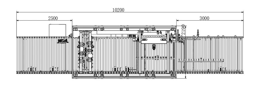
Three-View Drawings
Schematic Diagram of Production Process Mode
Detailed images
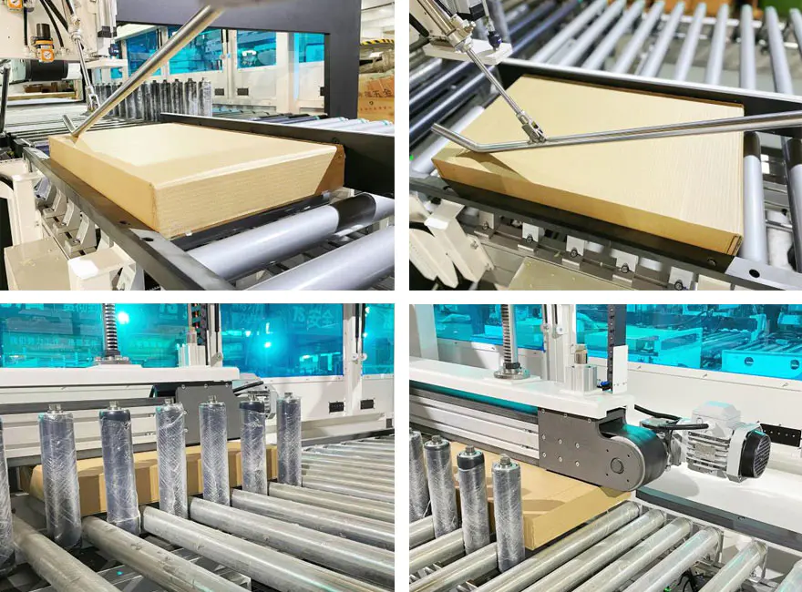
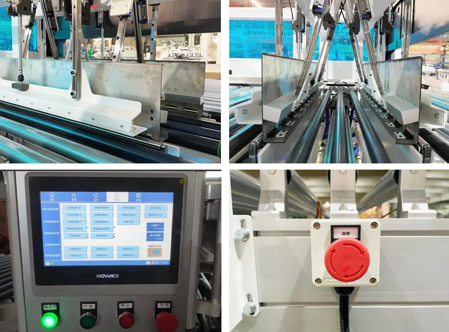
Measuring station
Detailed images
List of Wearable Parts and Consumables
| No. | Item | Specifications | Suggested Q’ty | U8 number |
| 1 | PTEE roller | BZ-LFXJ-01-03-01-01 | 2 |
|
| 2 | M16 double-ended stud | BZ-FXJ-G-015 | 2 |
|
| 3 | Teflon pressure wheel |
|
4 |
|
| 4 | Pressing belt (dual-guide type) | 95-L3990 (Thickness3) | 1 |
|
| 5 | Side alignment belt (triple-guide type) | 195-L3742 (Thickness3) | 1 |
|
| 6 | Strip elastic belt | 392*20*1.5 | 15 |
|
| 7 | Pressure reducing valve | GR20008F1 | 1 |
|
| 8 | Inlet throttle valve | PSL8-02A | 1 |
|
| 9 | Floating joint | F-M16X125F | 4 |
|
| 10 | Cylinder | SAI 50X350S | 1 |
|
| 11 | Cylinder | SAI50x300S | 1 |
|
| 12 | Slider | HGW30CC | 1 |
|
| 13 | Linear bearing mounting bracket | LHBBW20 | 1 |
|
| 14 | Steel-core spliced synchronous belt | S8M-3984-25(Open) | 1 |
|
| 15 | Slider | HGH25CA | 1 |
|
| 16 | Steel-core seamless synchronous belt | 30-S8M-800 | 1 |
|
| 17 | Steel-core seamless synchronous belt | 30-S8M-872 | 1 |
|
| 18 | Magnetic switch | HX-31R-2M | 2 |
|
| 19 | Solenoid valve | 4V210-08B | 3 |
|
| 20 | Rubber shock absorber | SE-15(Blue) | 3 |
|
| 21 | Plug-in relay | RXM4LB2BD | 1 |
|
| 22 | Relay base | RXZE1M4C | 1 |
|
| 23 | Relay | RXT-F01 | 3 |
|
| 24 | Proximity switch | IME08-02BPOZT0S | 1 |
|
| No. | Item | Specifications | Suggested Q’ty | U8 number |
| 1 | Main unit filter mesh | 133272 | 1 |
|
| 2 | Throat gasket | 127028 | 6 |
|
| 3 | Spray gun filter mesh | 126150 | 3 |
|
| 4 | AX nozzle module | 167400 | 6 |
|
| 5 | 24V solenoid valve | 150236 | 6 |
|
| 6 | Nozzle gasket | 100368 | 12 |
|
| 7 | Steel conduit gasket | 107332 | 6 |
|
| 8 | Right-angle nozzle 0.5MM | 130897 | 4 |
|
| 9 | Needle | 500661 | 1 |
|
| 10 | Piston pump repair kit | 112757 | 1 |
|
| 11 | AX nozzle repair kit | 167414 | 6 |
|
| 12 | Backflow valve kit | 163008 | 1 |
|
Hot Tags: Pro Automatic Box Closing Machine
Related Category
Unpowered Roller Conveyor Series
Scissor Type Hydraulic Lifting Table Series
Intelligent Factory Furniture Production Line Series
Intelligent Packaging Line Series
Powered Belt Conveyor Series
Intelligent Factory Furniture Production Line Series Single Machine
Roller Series
Door Solution
Automatic Plate Cleaning Machine
Send Inquiry
Please feel free to give your inquiry in the form below. We will reply you in 24 hours.